 ch
ch English

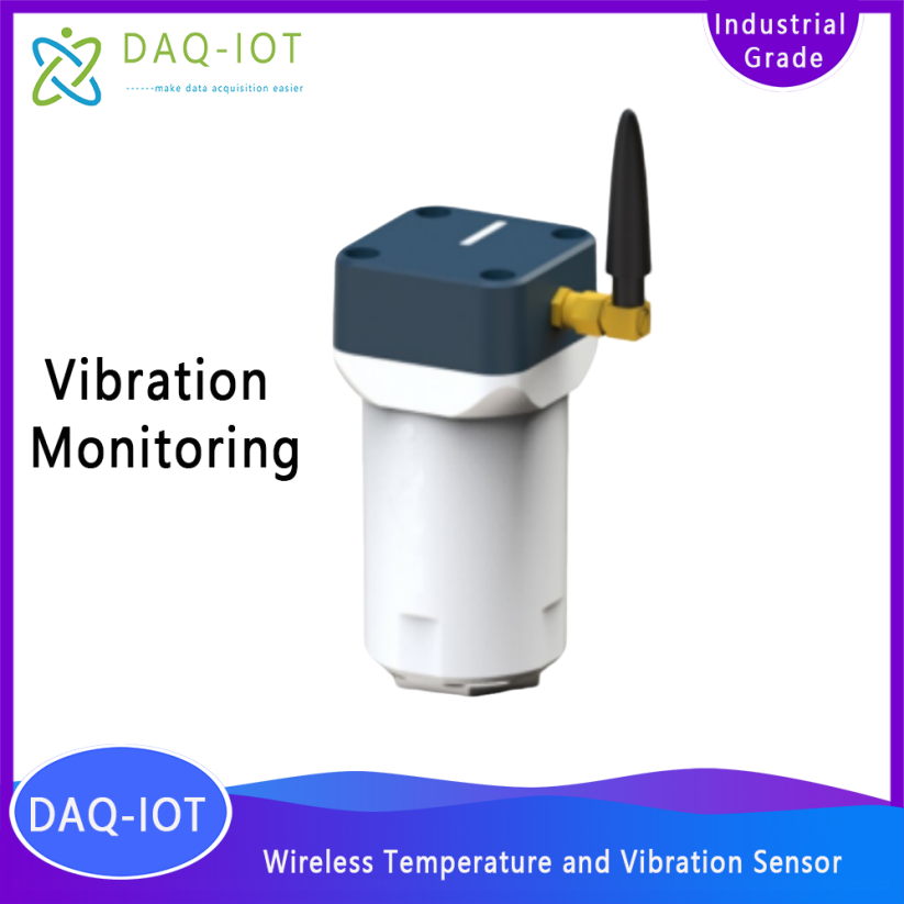
The wireless temperature and vibration sensor is an edge intelligent device launched by Shanghai Shucai IoT Co., Ltd. to monitor the health of rotating or reciprocating mechanical equipment (dynamic equipment). It adopts an integrated design, collects motor data in real time through multiple sensors, and learns and analyzes the data on the device side. The motor health data is transmitted remotely through NB-IoT, WIFI, 4G, 5G and other communication methods, and the analysis results are displayed on the cloud. It also has an early warning function for abnormal conditions of rotating or reciprocating mechanical equipment (dynamic equipment). It can adapt to various industrial environments and network environments, and has the characteristics of simple installation, low loss rate, and low false alarm rate.
Focus on predictive maintenance of motors/bearings in the following situations:
1. Various types of pumps used in oil and gas collection, including oil well pumps, plunger pumps, centrifugal pumps and other equipment;
2. High-pressure water pumps, centrifugal pumps, axial-flow pumps, mixed-flow pumps, screw pumps, positive displacement pumps and other equipment;
3. Chemical plant magnetic pumps, high-pressure reciprocating pumps, screw pumps, centrifugal pumps and other equipment;
4. Oilfield oil pumps, plunger pumps, centrifugal pumps and other equipment;
5. All kinds of wind turbine equipment;
6. Various motor/bearing equipment in other fields;
Our company solemnly promises:
You buy not only the product, but also the meticulous and thoughtful technical support service ! ! ! ( =^_^= )
This product only needs ordinary workers to connect the power and install it on site! No debugging is required!
We provide free remote guidance, remote configuration and debugging services, and send data to the user's designated cloud platform.
Free IoT solution consulting services!
model | DAQ-GP-VT4G | DAQ-GP-VTS4G | DAQ-LP-VT4G |
Communication | 4G Cat.1 | 4G Cat.1 | 4G Cat.1 |
Shell material | nylon | ABS | nylon |
Protection level | IP67 | IP65 | IP67 |
Working current | 150mA | 150mA | 150mA |
Power supply mode | External DC12V power supply | External DC12V power supply | 7200mAh |
Ambient temperature range | -40℃~+85℃ | -40℃~+85℃ | -40 ℃~+ 85 ℃ |
noise | 80 μg /√Hz | 80 μg /√Hz | 80 μg /√Hz |
Temperature measurement range | -40℃~+105℃ | -40℃~+105℃ | -40 ℃~ +105 ℃ |
Vibration range | ±8g | ±20g | ±8g |
Vibration frequency response range | 1Hz~1000Hz | 1Hz~1000Hz | 1Hz ~ 1000Hz |
Audio acquisition sensitivity | -26dBFS | -26dBFS | -26dBFS |
Signal-to-Noise Ratio (SNR) | 64dB(A) | 64dB(A) | 64dB(A) |
Audio receiving frequency range | 100Hz~80kHz | 100Hz~80kHz | 100Hz ~80kHz |
Magnetic flux measurement range | ±1300µT ( x,y -axis) , ±2500µT (z-axis) | ±1300µT (x, y-axis), ±2500µT (z-axis) | ±1300µT ( x,y -axis) , ±2500µT (z-axis) |
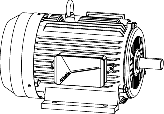
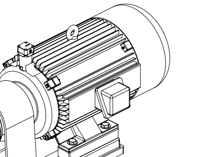
Installation location
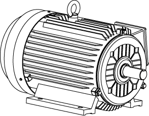
![]() : Look around and observe the external structure of the motor, select and determine the installation location of the detection equipment ( if there are daily inspections on site, you can refer to the daily inspection measurement points). It is recommended to install it in the horizontal direction of the motor and close to the monitoring components.
: Look around and observe the external structure of the motor, select and determine the installation location of the detection equipment ( if there are daily inspections on site, you can refer to the daily inspection measurement points). It is recommended to install it in the horizontal direction of the motor and close to the monitoring components.
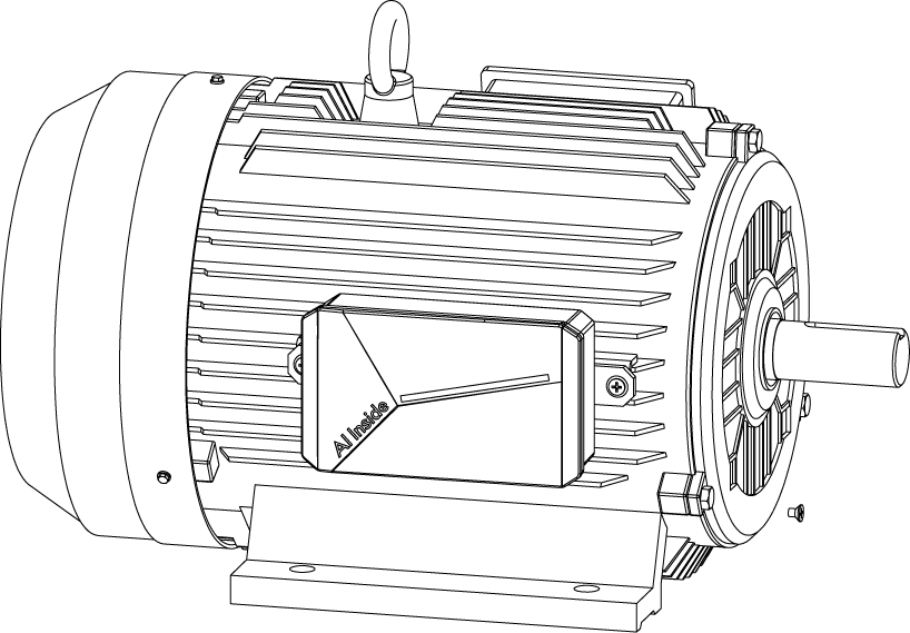
Apply AB glue
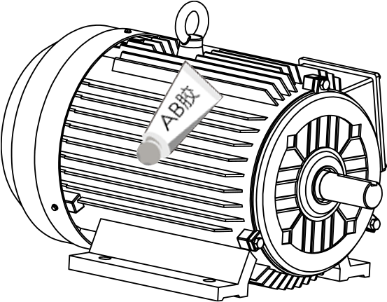
![]() : Apply AB glue evenly. If conditions permit, use a paint remover to remove the surface paint first, and then use sandpaper or a file to polish it to a smooth level. Clean the bonding surface and apply AB glue evenly (see the tube body for the use of AB glue ).
: Apply AB glue evenly. If conditions permit, use a paint remover to remove the surface paint first, and then use sandpaper or a file to polish it to a smooth level. Clean the bonding surface and apply AB glue evenly (see the tube body for the use of AB glue ).
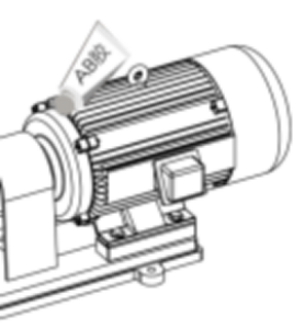
Paste the base
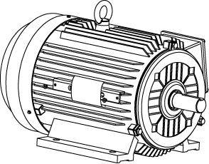
![]() : Place the base (the iron sheet shown in the picture) on the glue-coated area, press hard to adhere it, use auxiliary stickers to help fix it, let it stand for half an hour, and wait for the AB glue to solidify initially.
: Place the base (the iron sheet shown in the picture) on the glue-coated area, press hard to adhere it, use auxiliary stickers to help fix it, let it stand for half an hour, and wait for the AB glue to solidify initially.
Fixed bracket


![]() : Use M4*6 screws to connect and fix the bracket (the iron sheet shown in the figure) and the device . Apply a proper amount of thread fastener on the screw threads, and then tighten them with a cross screwdriver.
: Use M4*6 screws to connect and fix the bracket (the iron sheet shown in the figure) and the device . Apply a proper amount of thread fastener on the screw threads, and then tighten them with a cross screwdriver.
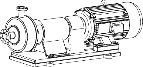
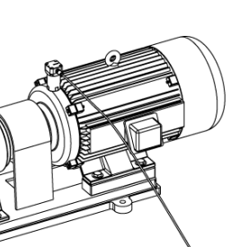
Installation combination
![]() : Fix the fixed device with M4*4 screws and the motor (the motor should be placed in the front as much as possible ); After the device is installed, connect the power cord.
: Fix the fixed device with M4*4 screws and the motor (the motor should be placed in the front as much as possible ); After the device is installed, connect the power cord.
Motor Look Around
Look around at the motor's external structure, select and determine the installation location of the detection equipment ( if there are daily inspections on site, refer to the daily inspection measurement points). It is recommended to install it at the motor bearing end cover and as close to the monitoring components as possible.
Gluing
Preparation before bonding. If conditions permit, use a paint remover to remove the paint on the motor surface, and then use sandpaper or a file to polish it to a smooth surface. Clean the bonding surface and evenly apply AB glue (see the tube body for the use of AB glue ).
Paste the device, use auxiliary stickers to help fix it, and let it stand for half an hour.
Place the device on the glue-coated area, press hard to adhere it, use auxiliary stickers to help fix it, let it stand for half an hour, and wait for the AB glue to initially solidify.
Connect power
The equipment is bonded and the power cord is connected.
电话 : Facebook/wechat/WhatsApp:+8619936624847 LINE:daqiot
邮箱 : business@daq-iot.com
手机 : +8619936624847
地址 : Room 501-50, No.9, Lane 60, Hulan West Road, Baoshan District, Shanghai。Address : Apt. 8A, House 9, Road 105, Gulshan 2, Dhaka, Bangladesh
Copyright © 2025 DAQ-IOT All Rights Reserved. 沪ICP 2021036991号
