1 Product Overview
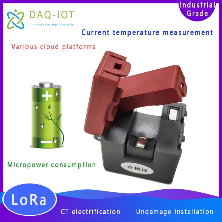
The SC-LP-CTLoRa wireless current temperature acquisition sensor terminal is equipped with a low-power, high- sensitivity open-type transformer . It converts the large current on the primary side into a small current on the secondary side through the principle of electromagnetic induction, and then uses it for current monitoring . It can very sensitively detect the size of the line current . If the monitoring loop current is greater than the product startup current, the sensor enters the normal working mode, collects temperature, current and other related data, and uploads them to the acquisition device through wireless communication. If the line is unloaded or the load current is less than the startup current, the sensor uses the internal battery to power the sensor to keep working.
The sensor terminal supports GPRS/4G/NB-IOT/LoRa/WiFi communication (GPRS communication is used by default for external power supply, and NB-IOT/LoRa communication is used by default for battery power supply) , overcoming the wireless communication shielding caused by the special environment on site, greatly simplifying the on-site deployment time and reducing construction costs . It has a wide current measurement range, uses high-quality magnetic core materials, and has an open-close structure, which is easy to install. It is used for current monitoring and collection in AC motors, lighting equipment, air compressors, heating, ventilation and air conditioning equipment, building self-control systems, industrial city networks, rural power grid transformation projects and other scenarios .
model | Features |
SC-LP-CTLoRa SC-LP-CTNB | NB-IOT / loRa communication, powered by long-life lithium batteries, suitable for occasions with low acquisition frequency and difficult external power supply. |
SC-GP-CT4G | GPRS communication, 220V AC/12V DC power supply, suitable for occasions with high acquisition frequency or convenient external power supply. Because the device is online by default, it can support remote configuration parameter debugging, and only needs to be installed and connected to the power supply on site. |
2 Service Concept
Our company solemnly promises:
You buy not only the product, but also the meticulous and thoughtful technical support service ! ! ! ( =^_^= )
This product only needs ordinary workers to connect the power and install it on site! No debugging is required!
We provide free remote guidance, remote configuration and debugging services, and send data to the user's designated cloud platform.
Free IoT solution consulting services!
3 Product Features
3.1 Current acquisition characteristics
Collection Type : Communication
Current range : AC1A~400A
Maximum input: 100% (continuous) / 150% (1 minute)
Current accuracy level: ±1%FS
Energy source: power frequency magnetic field or internal replaceable lithium battery (540mAh)
Maximum power consumption: ≤0.1W
CT power supply minimum starting current: 0.5A~1A,AC
Minimum starting current cold start time: ≤4min
Collection frequency: Power frequency magnetic field: 5s Battery: 3min
3.2 Temperature acquisition characteristics ( optional )
Collection type: Electrical contact point temperature
Temperature range: -40℃ to +150℃
Temperature accuracy level: ±2℃
3.3 Electrical Characteristics
Power supply: battery or 12V DC/220V AC
Insulation impedance: >100MΩ (primary/secondary)
3.4 Transformer communication characteristics
Wireless frequency : 433MHz
Transmission distance : 50m in open space
Wireless transmission method: LoRa
3.5 Gateway communication characteristics
Communication interface: default RS485
Wireless transmission method: GPRS/NB-IOT/LoRa/WiFi
Communication protocol : MQTT/TCP/UDP/HTTP/SSL/ModBus RTU, other protocols can be customized
Data forwarding: any public network server
Number of gateway server centers: can support reporting data to up to 7 cloud servers at the same time.
Heartbeat packet: supports custom heartbeat packets, which can be set to signal strength.
Registration package: supports custom registration package, which can be set to IMEI code.
Positioning: Support LBS base station positioning, convenient for querying device location.
3.6 Structural characteristics
Material: PC plastic (shell)
Main protection level: IP 42
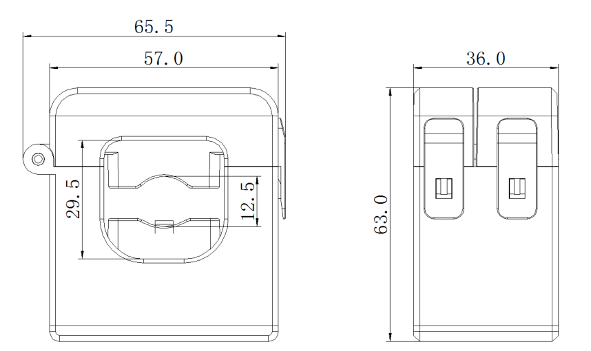
Body size: 65 mm × 36 mm × 63 mm
Transformer probe structure : open type
Main installation method: wall hanging or screw fastening
Transformer probe installation method: hanging installation
Temperature probe installation method: cable tie installation
3.7 Electromagnetic compatibility
Electrical fast transient burst immunity test
Implementation standards GB/T 17626.4; IEC 61000-4-4
Level: Level IV (communication port 2kV, other ports 4kV)
Electrostatic discharge immunity test
Implementation standards GB/T 17626.2; IEC 61000-4-2
Level: Level III (contact discharge 6kV, air discharge 8kV)
Radio frequency electromagnetic field radiation immunity test
Implementation standards GB/T 17626.6; IEC 61000-4-3
Level: Level III (10V/m)
Power frequency magnetic field immunity test
Implementation standards GB/T 17626.8; IEC61000-4-6
Level: IV
3.8 Work Environment
Ambient temperature -25 °C ~ 75 °C, humidity 0 ~ 95 % (non-condensing)
4 Core advantages of products
v Simple installation and quick deployment help IoT projects to be implemented quickly
v Supports live and lossless installation, and the user's equipment does not need to be powered off or shut down during installation
v The gateway supports custom registration packages and heartbeat packages, making it easier for the platform to distinguish devices
v The gateway supports any private IoT cloud platform and configuration software, and provides data protocol docking
v Non-intrusive measurement, does not affect the normal operation of the equipment
v The gateway supports remote configuration parameters and FOTA remote upgrades, minimizing the personnel costs of on-site construction and maintenance
5 Data reporting communication protocol
5.1 Protocol analysis instructions
There are multiple push methods such as UDP/TCP/MQTT/HTTP. To receive data, users need to provide the public IP (or domain name) address and port number of the cloud server.
Example of a data message in JSON format:
{"A":56.7,"B":55.8,"C":49.3,"D":1.2,"deviceID":"860344048491162"}
Message analysis:
{
"A" : 56.7 , //Current value of the first channel
"B" : 55.8 , //Current value of the second channel (optional)
"C" : 49.3 , //Current value of the 4th channel (optional)
"D" : 1.2 , //4th current value (optional)
"deviceID" : "860344048491162" //Device ID
}
5.2 Protocol customization
If you need to customize other communication protocols, please contact the sales staff. For orders of this product over 1,000 yuan, the communication protocol can be customized free of charge.
6 Platform docking
6.1 Default Platform
The product is connected to our designated industrial Internet of Things platform by default when it leaves the factory. The platform interface is as follows:
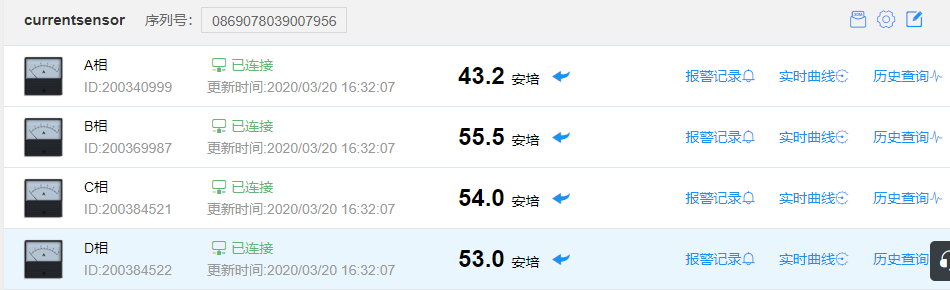
Computer browser interface
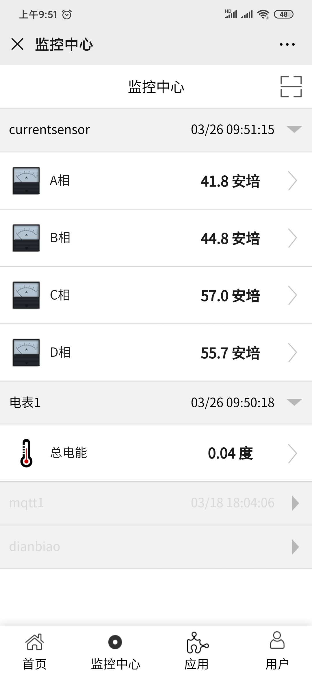
WeChat access interface on mobile phone
6.2 User-specified platform
Taking the Alibaba Cloud platform docking as an example, after the user creates a product and adds a device on the Alibaba Cloud IoT platform, the user needs to provide a triple: {ProductKey, DeviceName, DeviceSecret} and the MQTT topic to be published.
For example, the values of the triples are:
ProductKey = b0FMK1Ga5cp
DeviceName = 862991419835241
DeviceSecret = y7MTCG6Gk33Ux26bbWSpANl4OaI0bg5Q
7 Application Cases
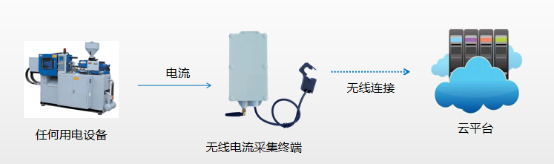
Equipment working status/duration monitoring
8 Installation and Maintenance
8.1 Battery Replacement
The sensor is powered by a high-performance lithium battery with a service life of up to 5 years. Please replace the battery when the service life expires.
Note: When the measured current is greater than the starting current of 1A , the sensor enters the normal working mode, collects temperature, current and other related data regularly , and uploads them to the gateway device wirelessly . If the line is unloaded or the load current is less than the starting current, the sensor uses the internal battery to maintain a low-power working state.
8.2 Indicator Lights
The sensor provides an indicator light, which flashes when wireless communication is in progress.
Possible issues | Possible causes | Possible solutions |
The indicator light does not flash after power on | Low battery | Check if the button battery is powered. If it is powered by battery only, you need to wait for
180 seconds for the indicator light to flash. |
The measured current is less than the starting current | Check whether the measured current is greater than the starting current. |
After adding the signal, the measured data is inaccurate or displayed as 0. | Incorrect temperature measurement | Check whether the temperature sensor is in close contact with the cable under test.
Check whether the temperature measurement signal is within the measurement range of the device. |
Inaccurate current measurement | Check whether the transformer buckle is fastened.
Check whether the current measurement signal is within the measurement range of the equipment. |
Incorrect power status | The distance between the live detection electrode and the tested cable is far | Check whether the tested cable has electricity.
Check whether the electrode is in contact with the cable
conductor. |
The sensor and the receiving device cannot communicate | Communication parameters are incorrect | Check if the mailing address is correct |
Communication link affected | Check whether the signals on both sides of the transmitter and receiver are shielded by metal.
Check whether the distance between the transmitter and receiver is too far. |
9 Device size
 ch
ch English