1 Product Overview
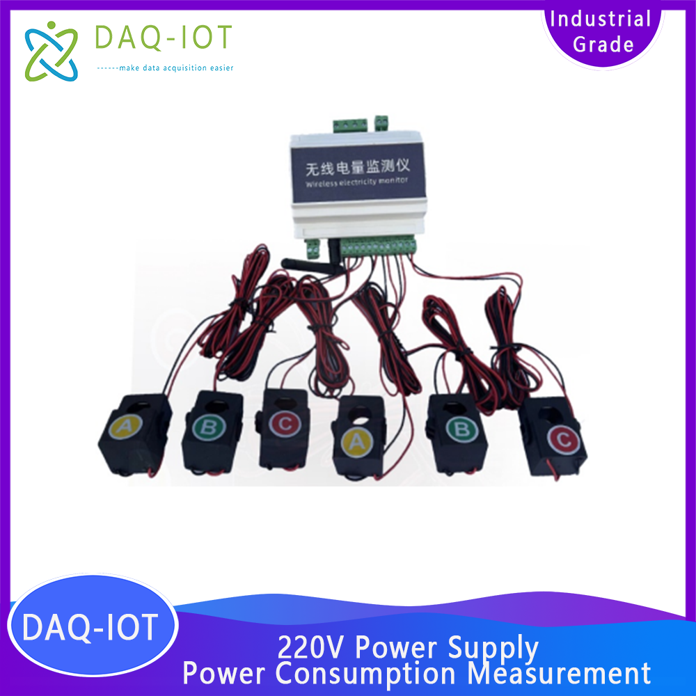
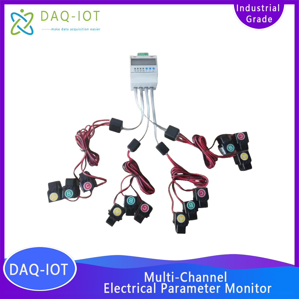
The multi-circuit AC wireless voltage and current sensor /electricity collection monitor is equipped with a multi-channel open-type transformer, which can monitor and collect three-phase voltage, current, power, electricity and other information, and can be used for energy consumption collection and monitoring. It supports RS485 and 4G network interfaces, and the data can be connected to the third-party cloud platform specified by the customer. This product can realize single-phase/ three-phase electricity consumption information monitoring, and is equipped with a 4G network interface that can be directly connected to the Internet of Things, and electricity consumption information can be directly viewed on WeChat or websites on mobile phones. It is suitable for scenarios where online remote monitoring of electricity information is required , easy to install, and beautiful in appearance .
2 Service Concept
Our company solemnly promises:
You buy not only the product, but also the meticulous and thoughtful technical support service ! ! ! ( =^_^= )
This product only needs ordinary workers to connect the power and install it on site! No debugging is required!
We provide free remote guidance, remote configuration and debugging services, and send data to the user's designated cloud platform.
Free IoT solution consulting services!
3 Product characteristic parameters
3.1 Acquisition characteristics
l Voltage measurement range: 1 10 ~ 250 VAC
l Current measurement range: 0 ~120 A ( other ranges can be customized )
l Voltage accuracy: ± 1V (default)
l Current accuracy: ± 0.1 A (default)
l Power accuracy: ± 1 W (default)
When wiring the RS 485 signal line, please note that the A and B lines cannot be connected reversely, and the addresses of multiple devices on the bus cannot conflict.
Serial number | Interface Definition | illustrate |
1 | A. B | RS485 communication interface A and B |
2 | U A, N | A-phase voltage detection is connected to the live wire and neutral wire equipment power supply interface |
3 | U B | B phase voltage detection connected to live wire |
4 | U C | C phase voltage detection connected to live wire |
5 | I 1+ 、 I 1- | Current 1 transformer access interface |
6 | I 2+ 、 I 2- | Current 2 transformer access interface |
7 | I 3+ 、 I 3- | Current 3 transformer access interface |
8 | I 4+ 、 I 4- | Current 4 transformer access interface |
9 | I 5+ 、 I 5- | Current 5 transformer access interface |
1 0 | I 6+ 、 I 6- | Current 6 transformer access interface |
1 1 | K 1 + , K 1 - | Spare relay output interface |
3.2 Electrical Characteristics
l Power supply: 2-20 VAC
l Device power consumption: < =3W (default)
3.3 Communication characteristics
l Output signal: RS485 modbus/4G network
Customizable WiFi/LoRa and other communication methods
3.4 Structural characteristics
l Host overall size: 1 10 × 1 15 × 60 mm
3.5 Storage environment
l Temperature -40 ℃ ~ 80 ℃
4 Core advantages of products
u Simple installation and quick deployment help IoT projects to be implemented quickly
u Supports custom registration packages and heartbeat packages to facilitate platform differentiation of devices.
u Support any IoT cloud platform and configuration software, and provide data protocol docking
u Supports Alibaba Cloud, Baidu Tiangong, OneNet, Tencent Cloud mainstream cloud platforms
u Support external multi-channel sensors
u Non-intrusive collection, does not affect the normal operation of the equipment
u Support remote configuration parameters and FOTA remote upgrade to minimize the personnel cost of on-site construction and maintenance
5 Communication Protocol
The data upload method supports mainstream communication methods such as RS485, TCP, UDP, HTTP, MQTT, etc. The data format can be connected to the third-party platform in the form of modbus or json.
5.1 Data reporting communication protocol analysis
JSON format data message parsing example :
{
"fac5":1, // Power factor 5
"current3":0.04, // current 3 A
"fac4":1, // Power factor 4
"power2":0, // Power 2 W
"energy6":0, // Power consumption 6 kwh
"current2":0, // current 2 A
"fac6":1, // Power factor 6
"power5":0, // Power 5 W
"energy5":0, // Power consumption 5 kwh
"fac3":1, // Power factor 3
"volA":223.9, // Phase A voltage V
"power6":0, // Power 6 W
"power3":0, // power 3 W
"current4":0, // current 4 A
"power4":0, // Power 4 W
"id":"861658062222974", // Device ID
"volC":0.2, // C phase voltage V
"fac2":1, // Power factor 2
"energy4":0, // Power consumption 4 kwh
"volB":0.1, // Phase B voltage V
"fac1":1, // Power factor 1
"current6":0, // current 6 A
"energy1":0, // Power consumption 1 kwh
"power1":0, // power 1 W
"energy2":0, // Power consumption 2 kwh
"current5":0, // current 5 A
"current1":0 // current 1 A
}
6 Applications
It can be used for power monitoring needs in various places , such as distribution cabinets, secondary cabinets, and terminal distribution boxes. Such as: low-voltage power distribution in transformer and distribution room, outgoing line circuits, residential buildings or communities, smart parks, industrial parks, agricultural technology greenhouses that need to realize intelligent power control, distribution areas such as hotels and tourist areas, shopping malls, factories, banks, office buildings and other comprehensive buildings, hospitals, schools and other crowded places, museums, cultural centers and other national cultural relics protection units, brick-wood or wooden structure buildings, and other power cables or equipment with high fire risks that need to set up monitoring nodes.
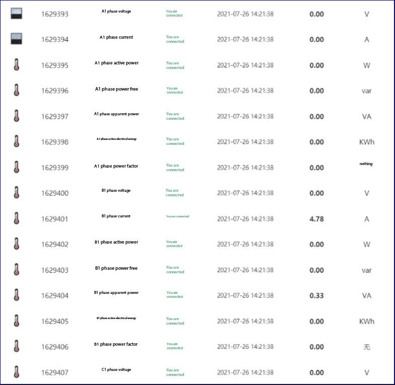
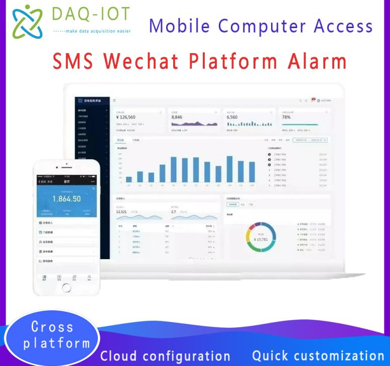
Platform web page data display example
7 Installation Notes
Please disconnect the power supply when wiring the product! Please ask a professional electrician to do the wiring to prevent short circuit.
 ch
ch English